Following Part 1 of our blog series, we will go through the process of setting up the software for our NIOS II processor. As a refresher, the Nios II processor is an Altera soft controller that is instantiated inside the FPGA. In our example, we are using the Nios II to read the DECA board’s sensor data and send it to the CC2650 wireless microcontroller (MCU) located on Arrow’s BeagleBone Bluetooth® low energy (BLE) / Wi-Fi® cape. The CC2650 device then transmits the sensor data via Bluetooth® low energy to a paired smart device.
The Nios II software development will be performed using Altera’s Eclipse based development tool. You can learn more about Nios II and the available development tools by using the following link:
To setup the Nios II’s software environment we need to create a new blank project with an associated board support package (BSP). The BSP is the link between the embedded software and the NIOS II hardware system that we created in Part 1 of our blog series. The BSP includes the component device drivers, memory layout, and initialization files for the Nios II system.
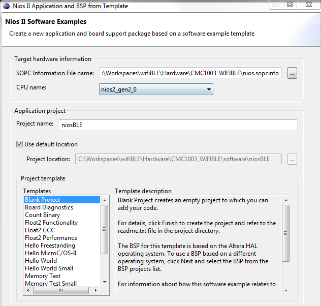
Figure 5: Altera’s Eclipse project window
In the figure above, we will use the nios.spocinfo file from our FPGA project in order to create our Nios II program template and BSP. The nios.sopcinfo file is generated from the QSYS tool which we discussed in the first blog post.
Once the blank project is created, we need to add some code in order for the Nios II to respond to queries from the CC2650 wireless MCU. The communication between the NIOS II and CC2650’s M3 is achieved using a single GPIO and a 4 wire, SPI interface. To begin a transfer of the ARM® Cortex®-M3 inside the CC2650 wireless MCU, toggles the GPIO line which triggers an interrupt service routine (ISR) on the Nios II. Upon receiving the interrupt, the Nios II will read the DECA board’s sensor data and transfer it to the SPI transmit register. This interrupt sequence insures that updated sensor data is going to be available each time the ARM Cortex-M3 initiates a SPI READ. After toggling the GPIO, the ARM Coretx-M3 acting as the SPI master will start an 8-bit SPI read. This read action cause the Nios II to begin shifting out the stored sensor data. This process occurs 10 times every 500msec.
Now let’s discuss some of the code required to achieve the transaction described above.
The code below sets up the ISR code on the NIOS II to service the ARM Coretex-M3’s interrupt (GPIO). Additionally, we register the IRQ with a service function (slinterrupt).
/********************************************
* Setup Interrupt Service
********************************************/
IOWR(CC2650_CTRL_PIO_BASE, 0, 0x00);
IOWR_ALTERA_AVALON_PIO_EDGE_CAP(CC2650_CTRL_PIO_BASE, 0xFF);
IOWR_ALTERA_AVALON_PIO_IRQ_MASK(CC2650_CTRL_PIO_BASE, 0xFF);
#ifdef ALT_ENHANCED_INTERRUPT_API_PRESENT
alt_ic_isr_register (CC2650_CTRL_PIO_IRQ_INTERRUPT_CONTROLLER_ID,
CC2650_CTRL_PIO_IRQ,
slInterrupt,
(void *)CC2650_CTRL_PIO_BASE,
(void *)0);
#else
alt_irq_register (CC2650_CTRL_PIO_IRQ, CC2650_CTRL_PIO_BASE, slInterrupt);
#endif
alt_ic_irq_enable(CC2650_CTRL_PIO_IRQ_INTERRUPT_CONTROLLER_ID,
CC2650_CTRL_PIO_IRQ);
We will now add the function to process the ISR.
#ifdef ALT_ENHANCED_INTERRUPT_API_PRESENT
static void slInterrupt(void* context)
#else
static void slInterrupt(void* context, alt_u32 id)
#endif
{
alt_u16 x_axis, y_axis, z_axis;
alt_u16 temperature, humidity;
unsigned int pioData;
static int count = 0;
/********************************************
* Acknowledge the interrupt
********************************************/
IOWR_ALTERA_AVALON_PIO_EDGE_CAP(CC2650_CTRL_PIO_BASE, 0xFF);
/********************************************
* Read Data & Write to Transfer Register
********************************************/
if (count == 0)
{
lis332arRead(&x_axis, &y_axis, &z_axis);
hdc1000Read(&temperature, &humidity);
}
else
{
count++;
}
switch (count)
{
case 0:
IOWR_ALTERA_AVALON_SPI_TXDATA(CC2650_SPI_BASE,
(temperature >> 8) & 0xff);
break;
case 1:
IOWR_ALTERA_AVALON_SPI_TXDATA(CC2650_SPI_BASE,
temperature & 0xff);
break;
case 2:
IOWR_ALTERA_AVALON_SPI_TXDATA(CC2650_SPI_BASE,
(humidity >> 8) & 0xff);
break;
case 3:
IOWR_ALTERA_AVALON_SPI_TXDATA(CC2650_SPI_BASE,
humidity & 0xff);
break;
case 4:
IOWR_ALTERA_AVALON_SPI_TXDATA(CC2650_SPI_BASE,
(x_axis >> 8) & 0xff);
break;
case 5:
IOWR_ALTERA_AVALON_SPI_TXDATA(CC2650_SPI_BASE,
x_axis & 0xff);
break;
case 6:
IOWR_ALTERA_AVALON_SPI_TXDATA(CC2650_SPI_BASE,
(y_axis >> 8) & 0xff);
break;
case 7:
IOWR_ALTERA_AVALON_SPI_TXDATA(CC2650_SPI_BASE,
y_axis & 0xff);
break;
case 8:
IOWR_ALTERA_AVALON_SPI_TXDATA(CC2650_SPI_BASE,
(z_axis >> 8) & 0xff);
break;
case 9:
IOWR_ALTERA_AVALON_SPI_TXDATA(CC2650_SPI_BASE,
z_axis & 0xff);
break;
}
With the Nios II code wrapped up, all that remains is to add some code for the CC2650 wireless MCU. In Part 3 of our blog series, we will cover the steps required to open a template project in TI’s Code Composer Studio tool and then modify the design for use with our FPGA project.