This is the third and final post for our blog series describing how to add the SimpleLink CC2650 wireless microcontroller (MCU), a Bluetooth® Smart device, to your Altera FPGA project. In Part 1, we discussed building the hardware portion of our FPGA project. Next, in Part 2 we covered how to set up the Nios II software project and then added some code to allow it to read the DECA’s onboard sensors and communicate via SPI with a CC2650 device. In our final installment, we will discuss setting up the CC2650 wireless MCU’s software project and how to modify that project so it will communicate with our FPGA design.
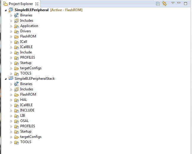
To begin, let’s setup the CC2650 wireless MCU project using TI’s Code Composer Studio software development tool. We will be using the SimpleBLEPeripheral as our starting reference. The reference project is in the BLE CC26xx SimpleLink package from Texas Instruments. The reference design consists of an application project and the BLE-Stack code.
Figure 1: Code Composer Studio project window
We will be modifying the application project to properly map the IO pin for the interrupt and configure the SPI peripheral as a master. The IO pin changes required are located in the Board.h file.
// ISR
#define Board_ISR_ON 1
#define Board_ISR_OFF 0
#define Board_ISR1 IOID_15
// SPI Board
#define Board_SPI0_MISO IOID_4
#define Board_SPI0_MOSI IOID_3
#define Board_SPI0_CLK IOID_5
#define Board_SPI0_CSN IOID_2
#define Board_SPI1_MISO PIN_UNASSIGNED
#define Board_SPI1_MOSI PIN_UNASSIGNED
#define Board_SPI1_CLK PIN_UNASSIGNED
#define Board_SPI1_CSN PIN_UNASSIGNED
The SPI peripheral is disabled in the reference project, so we will need to enable it. The csnPIN must be reassigned in the Board.c file.
/* SPI configuration structure, describing which pins are to be used */
const SPICC26XX_HWAttrs spiCC26XXDMAHWAttrs[CC2650_SPICOUNT] = {
{ /* SRF06EB_CC2650_SPI0 */
.baseAddr = SSI0_BASE,
.intNum = INT_SSI0,
.defaultTxBufValue = 0,
.powerMngrId = PERIPH_SSI0,
.rxChannelBitMask = 1<<UDMA_CHAN_SSI0_RX,
.txChannelBitMask = 1<<UDMA_CHAN_SSI0_TX,
.mosiPin = Board_SPI0_MOSI,
.misoPin = Board_SPI0_MISO,
.clkPin = Board_SPI0_CLK,
.csnPin = Board_SPI0_CSN
},
The following code is added to initialize the SPI peripheral and IO pin.
SPI_Params spiParams;
// Configure SPI parameters
SPI_Params_init(&spiParams);
// Master mode
spiParams.mode = SPI_MASTER;
spiParams.bitRate = SPI_SLAVE_CLK_RATE;
spiParams.frameFormat = SPI_POL0_PHA0;
// Attempt to open SPI
spiHandle = SPI_open(CC2650_SPI0, &spiParams);
// Open PIN handle
hGpioPin = PIN_open(&pinGpioState, BoardGpioInitTable);
We will add the following lines of code to toggle the IO and initiate the SPI transfer. The SPI configuration defaults to 8-bit transfers. This must be looped 10 times to extract all the data from the NIOS II. If you are wondering why it is looped 10 times, it’s because the data is 16 bit and is broken into bytes for the SPI transfer, thus we need to fetch: temperature (2 bytes), humidity (2 bytes), x axis (2 bytes), y axis (2 bytes) and z axis (2 bytes).
PIN_setOutputValue(hGpioPin, Board_LED1, Board_ISR_OFF)
PIN_setOutputValue(hGpioPin, Board_LED1, Board_ISR_ON);
PIN_setOutputValue(hGpioPin, Board_LED1, Board_ISR_OFF);
SPI_transfer(spiHandle, &spiTransaction);
In the RF002 design, we are using the custom UUID2 and UUID4 in the GATT profile to transmit the data over Bluetooth Smart. The characteristic property of UUID2 and UUID4 is setup to notify and transfer 6 bytes.
// Simple Profile Characteristic 2 Properties
static uint8 simpleProfileChar2Props = GATT_PROP_NOTIFY;
// Characteristic 2 Value
static uint8 simpleProfileChar2[SIMPLEPROFILE_CHAR4_LEN] = {0, 0, 0, 0, 0, 0};
// Simple Profile Characteristic 4 Properties
static uint8 simpleProfileChar4Props = GATT_PROP_NOTIFY;
// Characteristic 4 Value
static uint8 simpleProfileChar4[SIMPLEPROFILE_CHAR4_LEN] = {0, 0, 0, 0, 0, 0};
Every 500 msec, the following task is performed to notify all connected devices of any new data.
static void SimpleBLEPeripheral_performPeriodicTask(void)
{
uint8_t valueToCopy[20];
uint8_t tempValue[SIMPLEPROFILE_CHAR4_LEN];
uint8_t axisValue[SIMPLEPROFILE_CHAR4_LEN];
bspSPIRead(valueToCopy);
memcpy (tempValue, &valueToCopy[0], 4);
memcpy (axisValue, &valueToCopy[4], 6);
SimpleProfile_SetParameter(SIMPLEPROFILE_CHAR2, SIMPLEPROFILE_CHAR4_LEN,
tempValue);
SimpleProfile_SetParameter(SIMPLEPROFILE_CHAR4, SIMPLEPROFILE_CHAR4_LEN,
axisValue);
}
Hopefully, we have provided you with enough information to begin experimenting with your own projects using Arrow’s Max10 DECA board and the Arrow’s BeagleBone BLE /Wi-Fi Cape.
 Dallas Logic
